Morse code network
About this lesson
This lesson sequence is a hands-on approach to the learning about digital systems for years 7–8.
Year band: 7-8
Curriculum Links AssessmentCurriculum Links
Links with Digital Technologies Curriculum Area
| Strand |
Content Description |
|
|---|---|---|
| Years 7-8 | Knowledge and Understanding |
Explain how hardware specifications affect performance and select appropriate hardware for particular tasks and workloads (AC9TDI8K01). Investigate how data is transmitted and secured in wired and wireless networks including the internet (AC9TDI8K02). |
Learning sequence
Download LessonContent
Through hands-on experimentation and connected theory, the following concepts are explored:
- local area network (LAN)
- wide area network (WAN) and the internet
- network topology: bus vs star
- hubs, switches and routers
- packets and packet switching
- internet protocol (IP)
- transport control protocol (TCP)
- hacking through packet sniffing
- encryption.
Length
Approximately 4 x 45 minute lessons. (An extra lesson may be needed if devices are unfamiliar.)
Developed by DLTV for the Digital Technologies Hub
What you need
 |
Look out for safety precautions like this. |
 |
This indicates an enquiry opportunity for students to discuss and figure out a solution. |
 |
This gives key knowledge and points to further resources. |
-
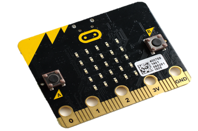
A class set (minimum eight) of BBC micro:bit devices is recommended for this sequence. Years 7–8 students may be familiar with this device from primary years. It might be used for other strands of the Digital Technologies curriculum in years 7–8.
Potential alternatives:
- CodeBug (a similar device to the micro:bit)
- Circuit Playgrounds Express
- Arduino Uno with ThinkerShield or other easy attachment for buttons, pins and LEDs (avoid breadboarding)
- another codeable device with
- at least one pin for digital reading safe voltage
- at least two pins for digital writing safe voltage
- at least one pushbutton
- at least two LEDs or an RGB LED.
 |
Testing was done with micro:bit and CodeBug. Both use 3V when running on batteries, and may be connected together. Other devices are untested. |
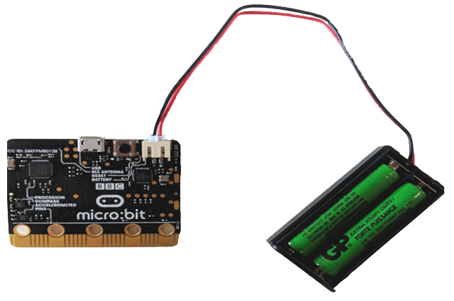
- Battery power for the devices. For practical reasons, this activity will be difficult to run with devices still attached to computers or laptops when testing.
The BBC micro:bit Go Kit comes with a battery pack for two AAA batteries to be attached.
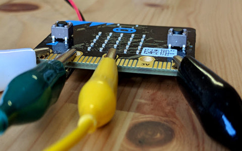
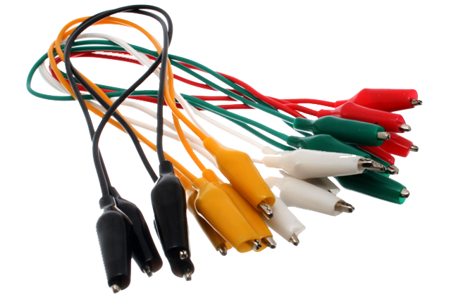
- Test leads with alligator clips. At least three leads per device is recommended.
- Computers or laptops to write code and transfer programs on to devices.
Note: micro:bit can also be coded from a mobile device or tablet.

Lesson One
Goals
- Discuss reasons for why computers are networked.
- Introduce Morse code as our metaphor for coded network signals.
- Program a micro:bit to send signals to another micro:bit via electrical lead.
- Practise sending Morse code signals between two micro:bits.
Introduction
 |
In the 1980s and early 1990s, most home computers were alone. They had no connection to other computers or devices, except peripherals like printers. Why do we network computers now?
|
Morse code
For this lesson sequence, we use Morse code to create network signals between our micro:bits.
Morse code was originally developed for the telegraph system.
- Each letter or number is represented by a specific sequence of dashes and dots.
- Each dot is made by tapping a button to send an electrical pulse.
- Each dash is made by holding down the button to send a longer electrical pulse.
- A longer pause indicates the next letter or number is on the way.
TASK
Using a Morse code chart, practise writing a short message to another student on paper.
Coding the micro:bits
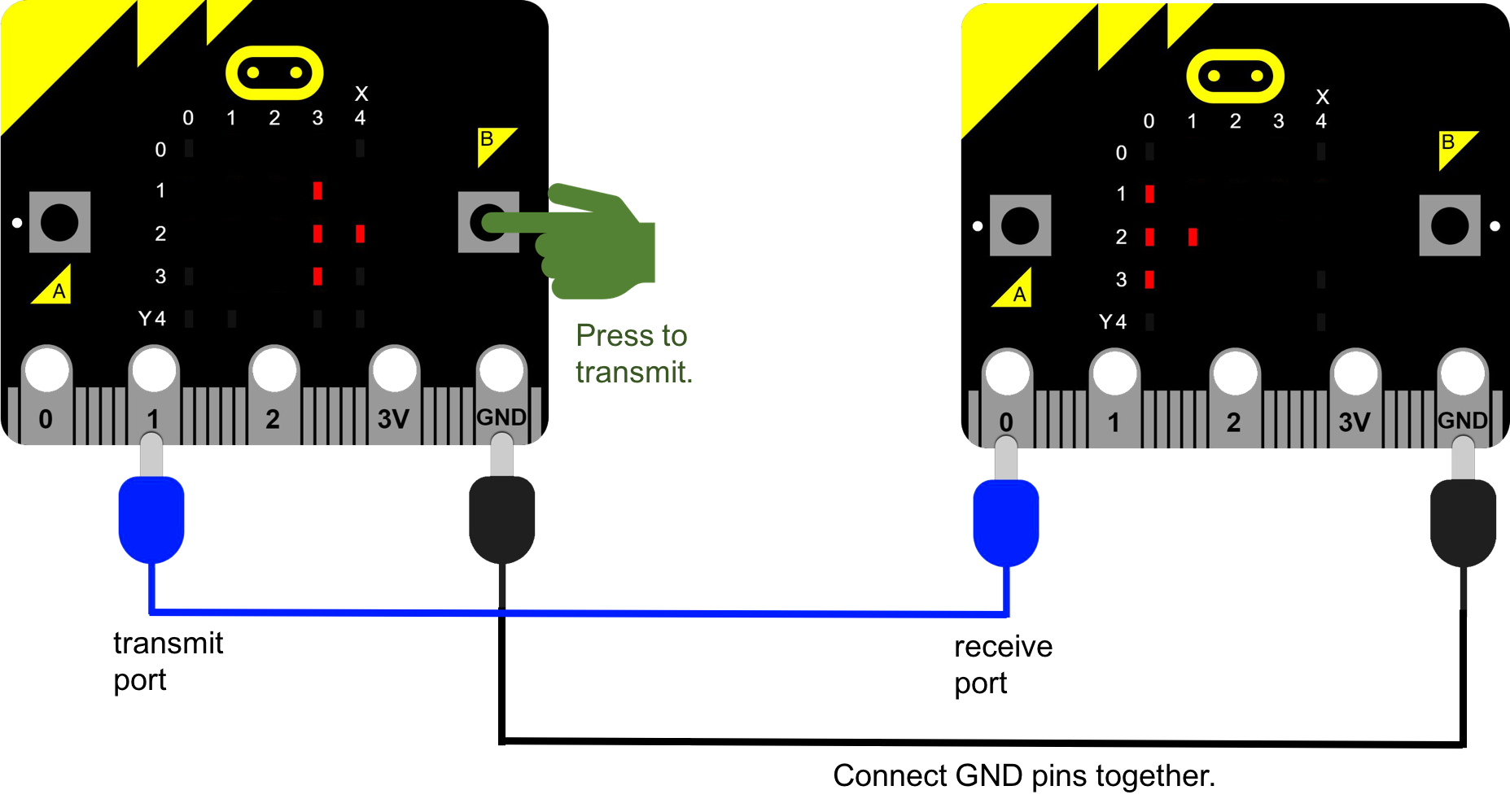
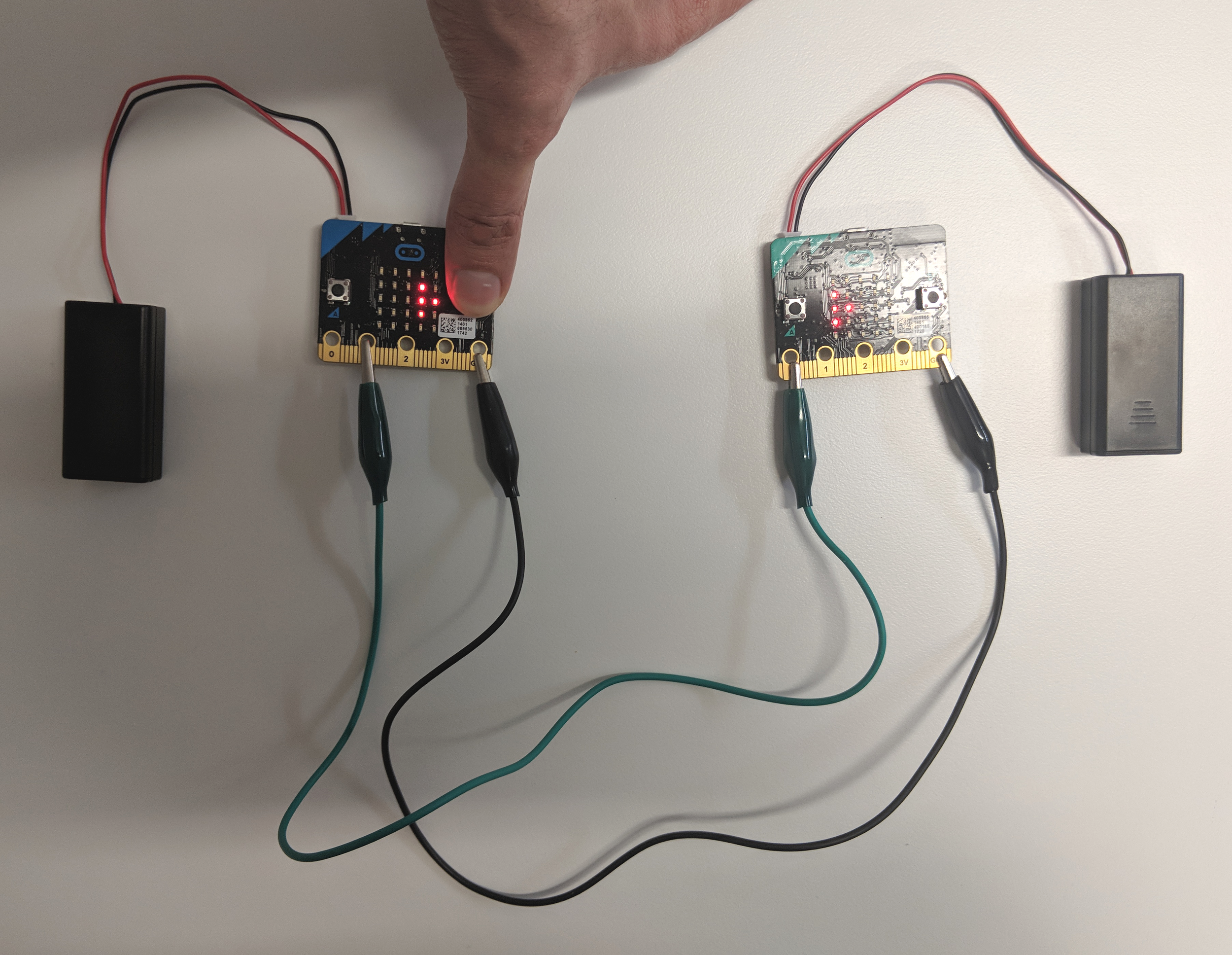
Two micro:bits will be connected together as shown below.
The device on the left will set Pin 1 (transmit port) to high when Button B is pressed. The device on the right will detect this on Pin 0 (receive port). The GND pins are tied together for electrical stability.
 /images/default-source/Lesson-ideas-details/morse-code-network/connected-microbits.png
Diagram 1: two micro:bits connected together
 |
Coding the micro:bits is an opportunity to address the Creating Digital Solutions strand (Victorian Curriculum) or the Processes and Production Skills strand (Australian Curriculum). To save time, code can be copied from this lesson sequence. |
 |
What does our transmit program need to do?
|
![This is visual programming code: Repeat forever (If: Button B is pressed [then: digital write pin P1 to 1; plot x3 y1; plot x3 y2; plot x4 y2; plot x3 y3]; [else: digital write pin P1 to 0; unplot x3 y1, x3 y2, x4 y2, x3 y3]).](/media/lrrfh55p/morse-code-network_diagram-2-transmit-program.png)
Diagram 2: Transmit Program |
 |
What does our receive program need to do?
|
![This is visual programming code: Repeat forever (If: Digital read pin P0 =1 [then: plot x0 y1; plot x0 y2; plot x1 y2; plot x0 y3]; [else: digital write pin P1 to 0; unplot x0 y1, x0 y2, x1 y2, x0 y3]).](/media/bnthfebq/morse-code-network_diagram-3-receive-program.png)
Diagram 3: Receive Program |
TASK
Work in groups that allow for two micro:bits to be connected together.
Save the transmit program to one micro:bit, and the receive program to the other micro:bit.
Test the code by connecting the two micro:bits as in Diagram 1.
Send the message you prepared on paper earlier, and see if you can correctly decode it.
Try sending a new message that the receiver doesn’t know!
 |
Always read product safety warnings before using classroom electronics hardware. Never connect a 3V (power) pin directly to a GND pin. |
Two-way communication
To talk back and forth, set up the two micro:bits as shown below.
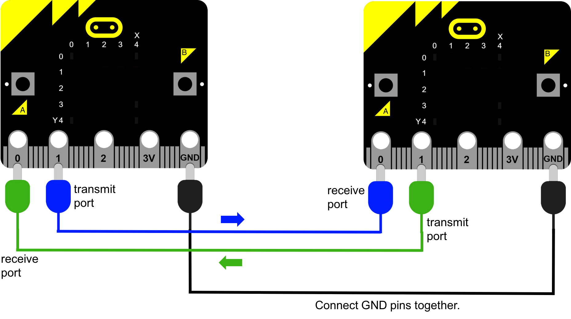
Diagram 4: two-way communication with micro:bits
 |
Can we combine the two programs so that a micro:bit can transmit and receive?Let’s say that transmitting takes priority over receiving.
|
![This is visual programming code: Repeat forever (If: Button B is pressed [then: digital write pin P1 to 1; plot x3 y1; plot x3 y2; plot x4 y2; plot x3 y3]; [else: digital write pin P1 to 0; unplot x3 y1, x3 y2, x4 y2, x3 y3 (if digital read pin P0 = 1); (then plot x0 y1; x0 y2; x1 y2; x0 y3); else (unplot x0 y1; x0 y2; x1 y2; x0 y3)]).](/media/zz2ouq0j/morse-code-network_diagram-5-combine-two-programs.png)
Diagram 5: Combine two programs so that a micro:bit can transmit and receive |
Lesson Two
Goals
- Introduce the concept of network protocols.
- Calculate bitrate.
- Introduce the concept of a local area network (LAN).
- Simulate a network hub.
Review of previous lesson
You may wish to begin by having students practise once more with the setup from last lesson. If necessary, put the transmit and receive program onto both micro:bits again, then practise sending a simple message in Morse code.
Introduction
 |
What do computers use for network signals, instead of Morse code?
|
 |
Binary is covered in the Data and Information strand (Victorian Curriculum) or the Knowledge and Understanding strand (Australian Curriculum). Data is stored in bits – 1s or 0s. To send a binary message, the 1s and 0s are pushed out as high or low voltages. A small whole number might be transmitted as a single byte of 8 bits (eg decimal number 57 = binary 00111001). 
A letter or other character might be encoded using a system like ASCII (eg letter ‘g’ = ASCII code 01100111).  |
 |
What are the challenges for humans trying to send messages to each other with binary?
|
Network protocols
 |
In our simulation, both transmitter and receiver already know they are using the same system – Morse code. When computers and devices talk, they must also establish a common way of talking. This is called a network protocol. |
 |
What usually happens at the beginning of a phone call?
Why do humans do this?
This is a protocol. Networked devices must also establish how they will communicate, by sending and receiving special signals at the beginning. |
 |
How do we measure how ‘fast’ a network connection is? The bitrate is the number of bits arriving per second (bps), not bytes per second.
|
 |
What is the speed of your internet connection at home?
At 20 Mbps, how long would it take to receive a 2 GB movie file?
1 Actually, it is 2 147 483 648 bytes (1024 Bytes = 1 kB, 1024 kB = 1 MB, 1024 MB = 1 GB). |
Setting up a LAN
Now we will simulate a local area network (LAN) with four micro:bits.
In this case, the communication is one-directional. The signal from the green micro:bit will be received by all three yellow micro:bits.

Diagram 6: Simulating a LAN
TASK
Work in groups that allow for three or four micro:bits together. Make sure all micro:bits have the transmit and receive program from Lesson 1.
Connect the three or four micro:bits as in Diagram 6, and make sure the message from the sender goes to all receivers.
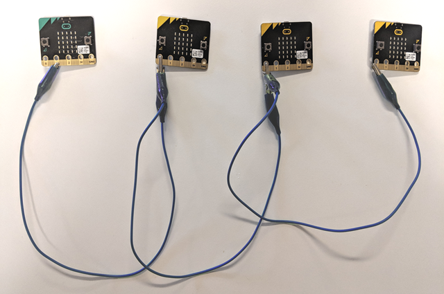
To make the coloured connections in the diagram above, you can use a “daisy chain”.
(Note, this photo shows only the blue connections. The black GND connections must be done also.)
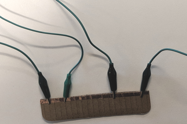
Alternatively, you can use a single conductive rail, such as the metal tape in this photo.
 |
A local area network (LAN) is the name given to a network of computers in the same geographical location. Connections may be wired or wireless. |
 |
Can you think of some examples of a LAN?
|
Collisions
 |
Our LAN works fine when one person is talking. What do you think will happen if two people try to talk at once?
|
Let’s try reversing the setup from the LAN simulation (Diagram 6). Can the yellow micro:bits all talk to the green one?

Diagram 7: reversing the set-up of Diagram 6
TASK
Connect the three or four micro:bits as in Diagram 7. Make sure all micro:bits have the transmit and receive program from Lesson 1.
Now try talking from the yellow (transmitting) micro:bits at the same time. Something is wrong.
(NOTE: Our micro:bit simulation only partially demonstrates this problem.
The yellow micro:bits that are not talking are holding the voltage low on the wire. This means that nothing gets through unless Button B is pressed on all three simultaneously.)
 |
When two signals try to use the same medium at the same time, it is called a collision. How do you avoid collisions when you are talking in a group?
|
 |
The problem of collisions was addressed as part of the ethernet protocol, a popular network protocol used around the world. The method is called Carrier-Sense Multiple Access with Collision Detection (CSMA/CD).
(The metaphor of the ‘talking stick’ was used in a competing protocol called Token Ring.) |
A hub
Our next simulation will be a network hub. A hub can be thought of as a powered repeater with multiple ports. Every signal going into it passes through to all attached devices.
The green micro:bit will send a message to the hub (red micro:bit). The hub will pass the message directly to the yellow micro:bits by outputting on Pin 1 and Pin 2.
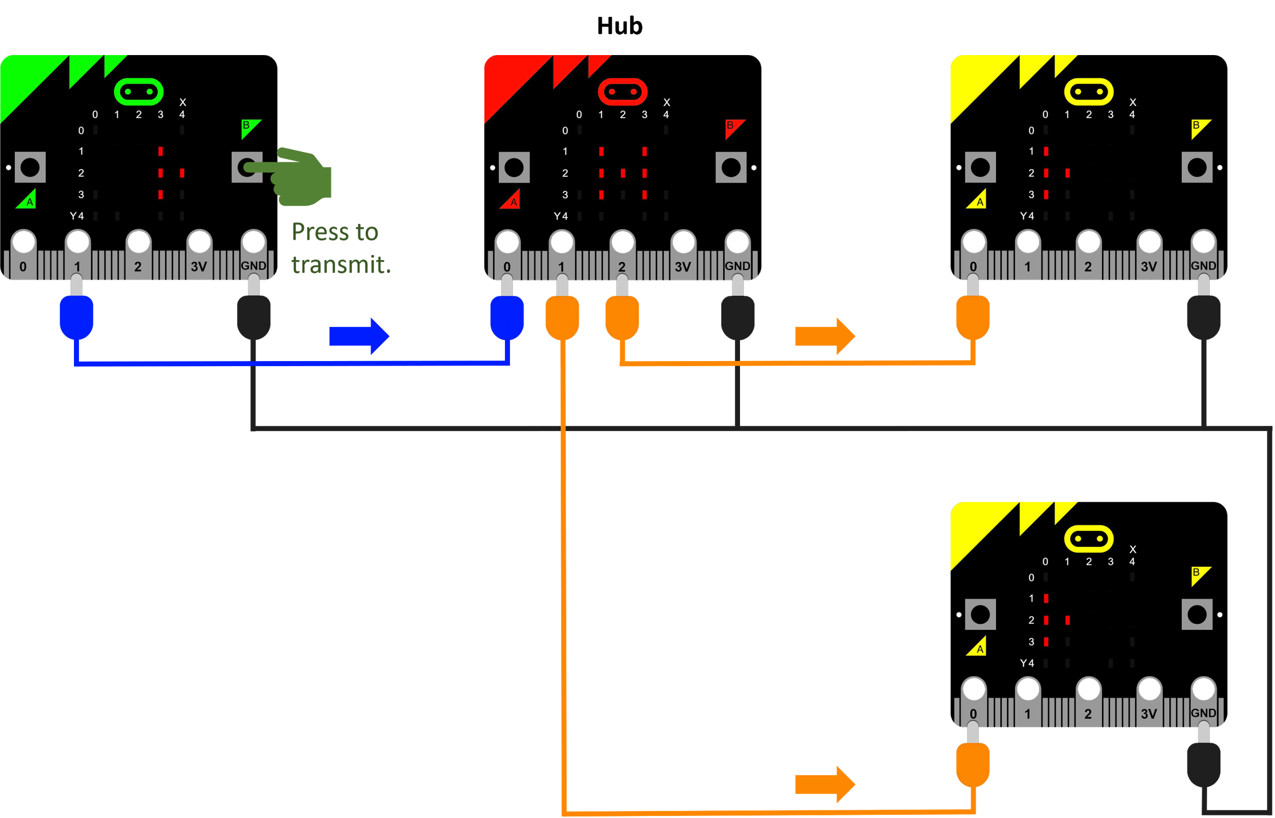
Diagram 8: network hub
 |
What does our hub program need to do?The hub will operate completely automatically, without any pushbuttons needed.
|
![This is visual programming code: Repeat forever (If: digital read pin P0 = 1 [then: digital write pin P1 to 1; digital write pin P2 to 1; plot x1 y1; plot x3 y1; plot x1 y2; plot x2 y2; plot x3 y2; plot x1 y3; plot x3 y3]; [else: digital write pin P1 to 0; digital write pin P2 to 0; unplot x1 y1, x3 y1, x1 y2, x2 y2, x3 y2, x1 y3; x3 y3])](/media/a1sadp2l/morse-code-network_diagram-9-hub-program.png)
Diagram 9: Hub program |
TASK
Work in groups that allow for four micro:bits together. The hub (red) micro:bit should have the hub program. All other micro:bits have the transmit and receive program from Lesson 1.
Connect the four micro:bits as in the diagram above, and make sure the message from the sender (green) gets to the receivers (yellow).
 |
Hubs were often used in the early days of networks to allow more devices to connect. Today, they are still used occasionally, eg to quickly add more network ports in a room. |
||
|
Pros Cheap Make more ports available quickly |
Cons Broadcast the same signal to everyone Exacerbate the collision problem |
||
Lesson Three
Goals
- Introduce the concept of packets.
- Simulate addressing packets.
- Introduce routers.
- Simulate packet switching.
Review of previous lesson
In the previous lesson, a problem was identified that was common in early LANs: collisions.
In this lesson, we’ll see how more intelligent devices are used to solve this problem.
Introduction
 |
Suppose you are building a house. Your supplier needs to send lots of bricks, wood and other materials, but there isn’t room for it all in one truck. What does your supplier do?
How does your supplier ensure that all the trucks get to your building site?
|
 |
In a modern network, messages are split into small parts called packets. Packets are part of a protocol called internet protocol (IP). This protocol enables the internet, by assigning addresses to packets, so they can be delivered to devices around the world. Each packet includes the data to be sent, but it also includes an IP address. This address specifies a device to go to, even on the other side of the world. |
Setting up an internet
Now we will simulate a tiny internet with all the micro:bits in the classroom. You could pretend that the devices are in different parts of the world.
We’ll connect the micro:bits into an interesting net as in the diagram below.
- The green micro:bit (address 04) is the source of the message. Load transmit and receive program.
- Yellow micro:bits are potential destinations. Load transmit and receive program.
- Red micro:bits indicate hubs. Load hub program.
- The manual hub in Sydney (address 08) requires a student to select from two incoming signals. Because only Pin 0 is available for receiving signals, the student will need to swap the alligator clips to receive a signal from either ‘Los Angeles’ or ‘Kuala Lumpur’.
- Don’t forget to tie all GND pins together.
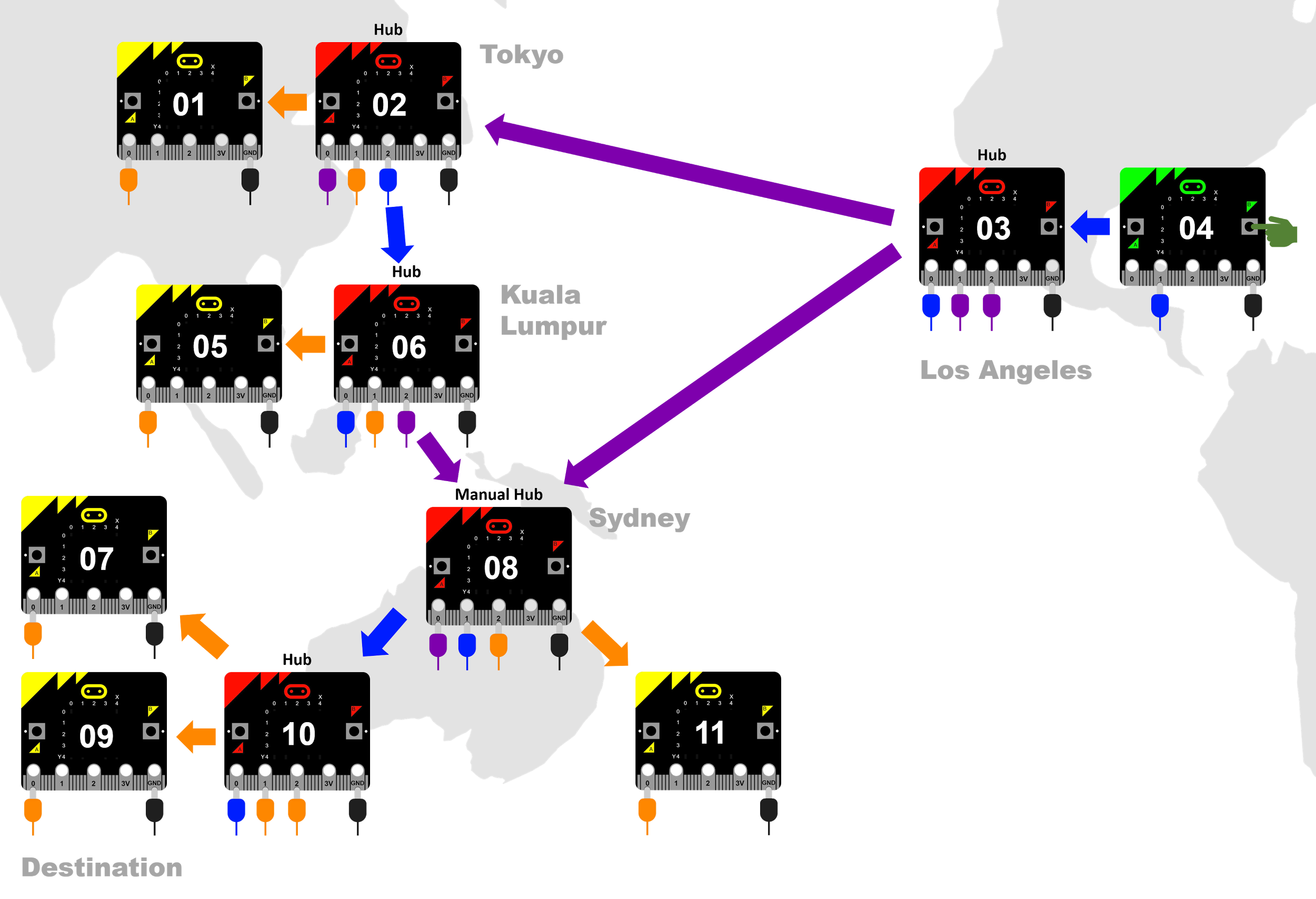
Diagram 10: Simulating the internet
 |
Jumper leads between desks may become a trip hazard. If possible, arrange desks together in the centre of the room, or in a U shape. |
TASK
Connect the class micro:bits in a net like the one in Diagram 9.
Also assign a simple numerical address to each micro:bit (eg 01, 02, 03), perhaps with sticky notes.
Write down a short message you will send from the green micro:bit, and break it into packets.
Add the address of the destination micro:bit to the front of each packet.
Convert your packets to Morse code, using a Morse code conversion table.
Send each packet separately. The students at each micro:bit should write down and decode all signals they receive.
 |
In this simulation, everyone would have received all the packets. What’s the problem with everyone receiving the packets?
Clearly, we need something smarter than hubs for our internet to succeed. |
 |
Enter routers. Routers have many advantages over hubs: |
|||
|
Pros They can direct a packet out of one port, instead of all ports. This is called packet switching. They actively learn which ports lead to which destinations, by communicating with their immediate neighbours. They also support security software (firewalls) to help secure a LAN. |
Cons Expensive compared to hubs. |
|||
We’ll replace our hubs (red micro:bits) with routers by changing the program.
 |
What does our router program need to do?Our router program will not automatically transmit an incoming message like the hub. Instead, the student with this micro:bit will need to:
Our program will need a variable to remember whether to transmit on Pin 1 or Pin 2. We’ll set it to Pin 1 at the start.
|
![This is visual programming code: On start (set transmission pin to 1). Repeat forever: If: button A is pressed, then [if transmission pin = 1; then set transmission pin to 2, basic.showString(“Now using Pin 2.”, 50)] else set transmission pin to 1, basic.showString(“Now using Pin 1.”, 50]. Then: If: button B is pressed, then [if transmission pin = 1]; [then digital write pin P1 to 1]; [else digital write pin P2 to 1]. plot x3 y1; plot x3 y2; plot x4 y2; plot x3 y3; Else: [digital write pin P1 to 0]; [digital write pin P2 to 0]. unplot x3 y1; x3 y2; x4 y2, x3 y3]; [if: digital read pin P1 to 0]; [then: plot x0 y1, x0 y2, x1 y2, x0 y3]; [else unplot: x0 y1, x0 y2, x1 y2, x0 y3]](/media/p04f1oop/morse-code-network_diagram-11-router-program.png)
Diagram 11: Router program |
TASK
Replace the hub program on the red micro:bits with the router program.
Retry the experiment in which students send a message in packets. This time, the students with the routers will need to send on each packet that comes in. They can use their own knowledge of our internet layout to decide which pin to use each time.
Try sending packets down different routes, but make sure they all end up at the destination.
 |
You can follow a real packet passing through routers on the internet by using the traceroute command. Try using the command to trace the route to an address that is definitely hosted overseas, such as www.thescotsman.co.uk. You may see routers in Sydney, California, New York and Britain. Note: the traceroute command sometimes fails, and may be blocked by settings at your school. |
IP addresses
 |
Our micro:bit addresses are simple, but real IP addresses are made up of four numbers, each between 0 and 255, eg 172.16.254.1 How many unique addresses can be made from those four numbers?
How many networked devices do you think there are in the world today? Don’t forget, they could be computers, TVs, fridges, phones, tablets, etc.
How is it possible that there are more unique devices than IP addresses? Routers are able to assign any IP addresses within a LAN, and remember them when packets come in from outside. All addresses within a LAN must still be unique to each other. Also, a new version of IP address (IPv6) contains many more digits, allowing for 3.4×1038 unique addresses. |
DNS servers
 |
We can type names like www.google.com to get to a device, rather than an actual IP address. This is thanks to Domain Name Servers (DNS), which keep registered domain names (like google.com) and match them to IP addresses. When you type in www.google.com, your web browser queries a DNS and finds the actual IP address. |
A switch (optional)
 |
Hang on, so what’s a switch? To save complicating things, we’ve brushed over switches. Switches are used extensively in large LANs like office buildings and schools, because they can have many more ports more cheaply than a router. At home, a single router is usually enough. A switch is smarter than a hub, but not as smart as a router. Switches are able to see the Media Access Control (MAC) addresses of devices. They can learn to send packets to specific devices within a LAN, but they cannot communicate to other networks. That requires a router. |
Lesson Four
Goals
- Introduce transport control protocol (TCP).
- Simulate sequencing packets.
- Simulate packet sniffing.
- Understand the rationale for encryption.
- Compare wired, wireless and mobile networks in terms of performance.
Review of previous lesson
In the previous lesson, a tiny internet was set up in the classroom. A message was split into addressed packets, and routers were used to send the packets to the correct destination.
In this lesson, we’ll solve a couple more problems and threats to our packets.
Introduction
 |
Last lesson, we began with a question about sending building materials to a construction site. The supplier splits the materials onto different trucks. She gives the address of the construction site to each truck, but the trucks may all take different routes to the address. Why might the trucks take different routes?
What problem might this cause at the construction site?
The same problem can occur with our packets. Routers may send them down very different routes to the destination. Unlike building a house, the receiver usually won’t know in which order to reassemble the packets of a message. What could be the solution?
|
 |
Numbering the packets for order is the job of another protocol called transport control protocol (TCP). TCP does its work of numbering the packets before IP adds the destination address to each one. TCP also adds bits to help determine if a packet became corrupted on its way. If so, a resend can be requested. TCP and IP work so closely together that they are often referred to as TCP/IP. |
One more time with the internet
Let’s connect the micro:bits into one more internet simulation. Diagram 9 in Lesson 3 is reproduced below. You might try a different layout.
- The green micro:bit (address 04) is the source of the message. Load transmit and receive program.
- Yellow micro:bits are potential destinations. Load transmit and receive program.
- Red micro:bits are routers. Load router program.
- The manual router in Sydney (address 08) requires a student to select from two incoming signals. Because only Pin 0 is available for receiving signals, the student will need to swap the alligator clips to receive a signal from Los Angeles or Kuala Lumpur.
- Don’t forget to tie all GND pins together.
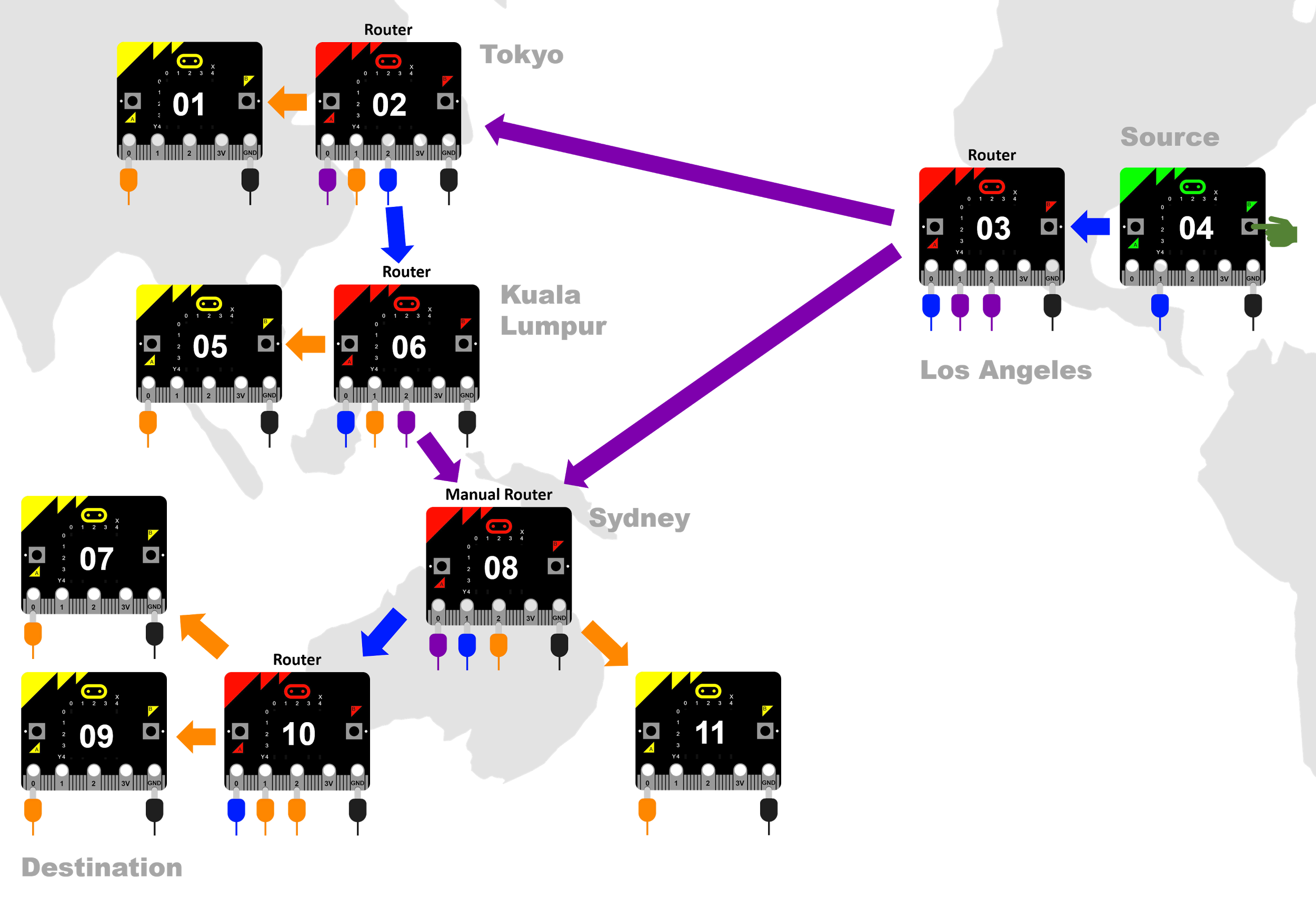
Diagram 12: Simulating the internet again
TASK
Connect the class micro:bits in a net like the one above.
Write down a short message you will send from the green micro:bit, and break it into packets.

Add the order sequence number to the front of each packet.
Add the address of the destination micro:bit to the front of each packet.

Convert your packets to Morse code, using a Morse code conversion table.
Send each packet separately, with some going via Tokyo and others direct to Sydney.
Once the packets reach the destination, decode each packet and strip off their addresses. Then use the order numbers to reassemble the packets.
Packet sniffing
 |
Suppose a hacker wanted to spy on the packets that arrive at the destination. How could they do that in our micro:bit network?
|
TASK
Try using a spare micro:bit to tap into your network and spy on packets going through.
 |
Spying on packets is called packet sniffing. It’s not only used by hackers, but also by network analysts trying to improve network performance. This form of tapping a network requires physical access to the hardware, but there are a number of more sophisticated ways to sniff packets, even in wireless networks. |
 |
How can a packet sniffer be thwarted? How can information be kept secure?
|
Encryption
 |
Encryption is a focus in the years 9–10 Digital Technologies curriculum. Here, we will do a simple example only. |
 |
Is Morse code already a form of encryption?
How could we encrypt the letters in our message?
|
TASK
Without your ‘hacker’ knowing the key, send a new encrypted message over your network.
 |
Encryption by simply moving letters is very weak. Why?
|
 |
Our micro:bit network simulation has been very simple compared to real digital networks. To finish this course, let’s compare some real technologies used for wired and wireless communication. |
|
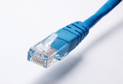
Twisted pair is a common, cheap cable used in ethernet networks. It uses pairs of copper wires, each pair twisted to reduce electrical interference.
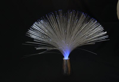
Optical fibre uses laser light pulses instead of electricity. Each fibre is a very thin tunnel with a reflective wall on the inside.
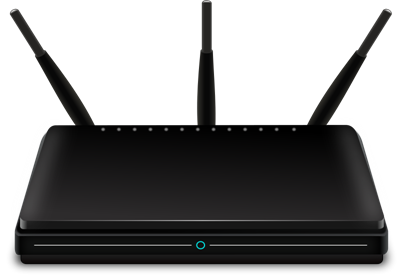
Wi-Fi (also called 802.11) uses radio waves in a small area. It works with the ethernet protocol, so IP and TCP work in a similar way to our simulation, but with radio signals instead of electrical current.
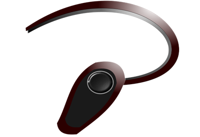
Bluetooth is a smaller-range wireless communication protocol, and relies on pairing two devices. It tends to be used for wireless peripherals (eg headphones, car audio, wireless mouse). The micro:bit can use Bluetooth.
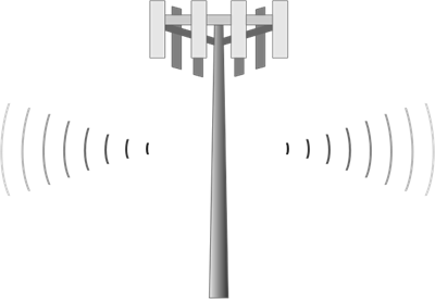
Cellular communication relies on radio towers. Mobile devices (like phones) move between the geographical areas (cells) covered by the towers.
 |
Some questions to research:
|
Review questions
Lesson 1
- What are the four main reasons for networking computers?
- What was Morse code originally developed for?
- Convert the following message into Morse code:
It is not down on any map; true places never are. (Herman Melville)
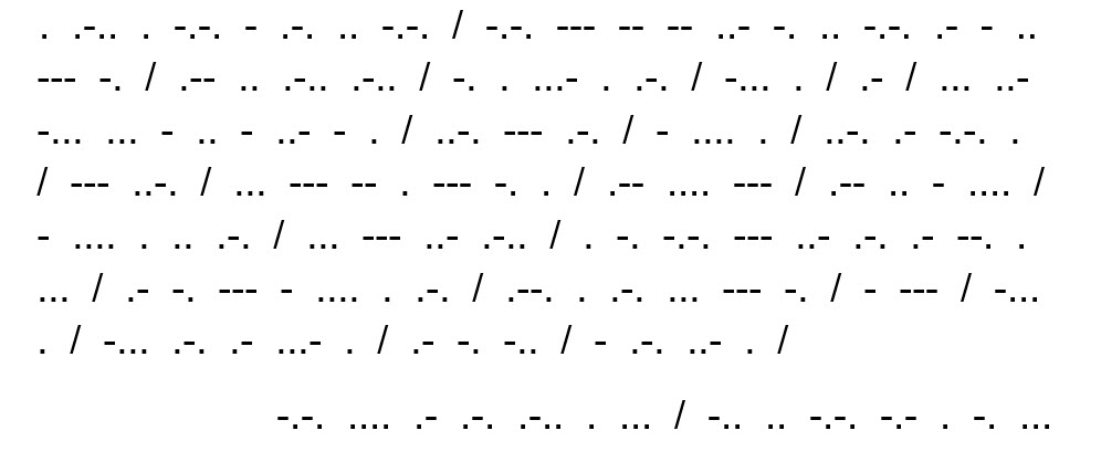
- Convert the following message into English:
Lesson 2
- Digital devices both store and send data in b__________, which is a system of 1s and 0s called b______. Eight b______ together make one b______.
- What is the name for an established set of rules allowing networked devices to talk together?
- True or false: A measure of the speed or bandwidth of a connection, bitrate is measured in bytes per second (bps)?
- What does LAN stand for?
- What is the name for a computer that provides file storage for multiple users to share?
- Explain the problem of signal collisions in networks.
- Explain how the problem of collisions was addressed within by CSMA/CD.
- Which network protocol is CSMA/CD a part of?
- List one advantage and one disadvantage of hubs in networks.
Lesson 3
- What is the name of the protocol responsible for addressing data packets so that they arrive at their destination across the world?
- How do routers solve the problem of signal collisions where hubs do not?
- How do routers know which route to send packets to reach their destination?
- How are real IP addresses different from the simple numbers used in our simulation?
- What translates names like google.com into actual IP addresses?
Lesson 4
- List two benefits of transport control protocol (TCP).
- What is packet sniffing?
- Encryption is one of three ways discussed for securing data on a network. What are the other two?
- Why isn’t optical fibre subject to electrical interference?
- Why don’t mobile phones only use Wi-Fi for data?
- The packets below have arrived at your device, which has address 06 in our simulation.
- First, decode the packets from Morse code.
- Then, use the sequence numbers to put the message in the correct order.


